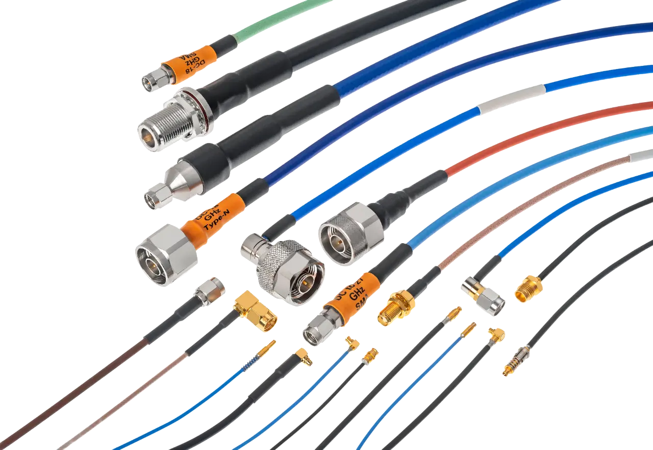
Flexible RF Cable Assemblies
Built to Bend, Engineered to Perform
Multi-purpose flexible RF cable assemblies.

Overview

 Routing through tight enclosures
 Navigating complex cable paths
 Systems subject to vibration or motion
 Repeated movement or installation cycles
Flexible RF cable assemblies are the go-to solution for microwave system engineers working in environments where high frequency RF, microwave, and millimeter wave signal performance can’t be compromised, but space, movement, and complexity are major design constraints.
In comparison to hand-formable, semi-rigid, or ruggedized/armored RF cable types, flexible RF assemblies are constructed for repeated movement, tight routing, and ease of install in critical commercial and military RF/microwave systems.
To that end, ConductRF Flexible RF cables are built with stranded center conductors, pliable dielectrics, and layered shielding, allowing them to bend, loop, and move with limited impact on signal performance.
Up to 110 GHz
As low as 0.25 dB/ft @ 3 GHz (varies by size & frequency)
±2° - ±12° over temperature or flex
20 - 30 dB typical
As low as 1.15:1
80 - 120 dB isolation depending on shielding type
.047 - .250 in.
0.2 - 2.5 in (depending on diameter and construction)
up to 1200 lbs/in² for armored flexible cables
- Solid copper or silver-plated copper (for low-loss, high-power)
- Stranded copper (for higher flexibility)
- Copper-clad steel (for rugged or semi-rigid variants)
Single braid, double braid, foil, or combination
up to 120 dB of isolation, depending on cable and shield construction
Low-PIM (< -160 dBc) versions available for DAS and high-precision systems
Anatomy of a Flexible rf cable

- 1
Outer Jacket
FEP, polyurethane, or PVC for abrasion resistance and environmental sealing
- 2/3
Shielding
(2) Braid and/or (3) foil layers for EMI protection and signal containment
- 4
Dielectric
Solid or foamed PTFE for low loss and impedance control
- 5
Center Conductor
Stranded copper for high flex life and mechanical durability
- +
Optional Enhancements
Double and triple shielding, low-PIM structure, weatherproof jackets, and molded strain reliefs.
Options & Customization
Jacketing Options
Jacketing Material | Properties | Ideal Use Case |
|---|---|---|
LSZH | Low smoke, zero halogen | Naval/Marine, medical, aerospace, public spaces |
PVC | Economical, general purpose | Indoor telecom, OEM |
PE | UV resistant | Outdoor base stations |
FEP | Chemically resistant | Industrial or cleanroom |
PTFE | Extreme temperature | Defense, aerospace, vacuum-rated |
Strain Relief, Boots, and Marking Options
Option Type | Description | Benefits | Typical Use |
|---|---|---|---|
Overmolded Boots | Molded plastic or rubber boots around connector | Improved strain relief, sealed ingress protection | Ruggedized field use, outdoor |
Molded Strain Reliefs | Pre-formed relief collars | Prevents flex-point damage | Lab, rack-to-rack systems |
Color Coded Sleeves | Color plastic or silicone identifiers | Fast visual cable ID | Test labs, telecom panels |
Heat Shrink ID Labels | Printable or custom ID wraps | Durable labeling | Aerospace, medical, precision systems |
Laser or Inkjet Marking | Permanent direct-to-cable marking | Clean and compliant | Defense, industrial environments |
Connector Mating Types
Mating Interface | Frequency Range | Application Notes |
|---|---|---|
SMA | DC 18 GHz | General use, telecom, military |
N Type | DC 11 GHz | Rugged field applications |
TNC | DC 11 GHz | Similar to SMA but with threaded security |
SMP/SMPM | DC–40 / 65 GHz | Miniature, high-frequency board-to-board |
2.92mm (K) | DC–40 GHz | Precision testing |
2.4mm | DC 50 GHz | Ultra-high-frequency lab testing |
1.85mm (V) | DC 67 GHz | Aerospace and test setups |
Cable to Connector Termination Styles
Termination Style | Description | Ideal Use Case |
|---|---|---|
Crimp | Connector ferrule compressed around braid | Field serviceable, fast assembly, used with all common cable sizes |
Solder | Core and/or braid soldered into place | Higher performance, permanent |
Clamp | Mechanical clamp secures braid | Reusable, lower cost |
Compression | Tool-less press-fit connection | Quick install, serviceable |
Field replaceable | Modular connector ends | Maintenance or rework systems |
Overmolded | Fully sealed with molded boot | Rugged, waterproof, outdoor use |


