
Low Loss Is Relative: Understanding the True Nature of RF Cable Assembly Loss
Introduction: The Myth of “Low Loss”
Every RF engineer has seen the claim—“low-loss coaxial cable.” But what does 'low' really mean? In truth, loss is never eliminated—only managed. The art of system design lies in understanding where and why attenuation loss occurs so you can control it rather than chase marketing labels.
What “Low Loss” Really Means
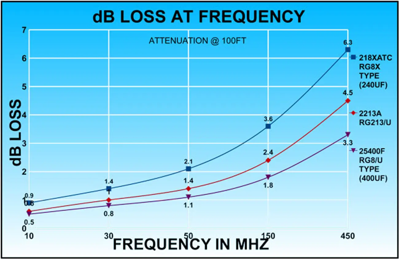
A coaxial cable’s loss, or attenuation, is not a fixed rating—it’s the product of its length, frequency, conductor material, and dielectric design. Manufacturers publish attenuation in dB per meter (or foot) at reference frequencies; as operating frequency increases, so does loss.
Key contributors:
- Cable Length (Linear Effect): Double the length ≈ double the loss.
- Frequency (Skin Effect): Higher GHz → thinner current paths → greater resistive loss.
- Conductor Material: Silver-plated copper minimizes resistance better than tinned or steel.
- Dielectric: Low-density PTFE and air-enhanced designs reduce dielectric absorption.
- Shielding & Connectors: Poor braid coverage or mismatched connectors add loss and reflections.
- Temperature: Fluctuations impact loss
Temperature: The Often-Ignored Variable
Real systems don’t operate at 25 °C forever. As temperature rises:
- Copper resistivity increases ≈ 0.4 %/°C → higher attenuation.
- Dielectric constant changes, especially near PTFE’s +19 °C transition.
- Mechanical expansion can shift impedance and phase over long runs.
A cable that’s “low loss” in the lab can drift in gain or phase on an aircraft or tower. That’s why ConductRF characterizes ΔLoss and ΔPhase per 100° C and uses stable PTFE dielectrics and silver-plated conductors for true temperature-controlled performance.
System-Level Thinking: Your Total Loss Budget
Context Makes “Low Loss” Relative
A 0.25 dB/m cable may be low loss for a 2 GHz test setup, but unacceptable for a 30 GHz link. Conversely, shortening a higher-loss flexible cable by half often beats a stiffer alternative’s performance. “Low loss” only matters relative to frequency, length, temperature, and mechanical need—and to the system’s signal-to-noise and power requirements.
Design Smarter with Maestro
ConductRF’s Maestro Cable Composer lets you:
- Input frequency and length, cable, style, and connectors to calculate insertion loss for a variety of assembly choices.
- Compare multiple cable families (flexible, hand-formable, semi-flexible, and semi-rigid).
- Export data to build your loss budget or spec sheet.
It’s the fastest way to translate theory into a design that works—in the lab and in the field.
Key Takeaway
“Low loss” isn’t a feature—it’s a relationship between physics, environment, and application. By accounting for frequency, length, temperature, and connectivity, engineers can design systems that perform predictably instead of optimistically.
Compose your next RF cable assembly in Maestro and see how real-world loss looks before you build.

About Dean Gammell
Dean Gammell leads customer facing efforts for ConductRF and manage the product support strategy focused on key customers and markets with a heavy emphasis on application engineered solutions.
Join our mailing list
Sign up for news, resources and tips, straight to your inbox.
We’re committed to developing the best RF Cable Assemblies and technical resources. Subscribe today. You won’t want to miss a thing.