

Six RF Cable Assembly Design Mistakes and How to Avoid Them
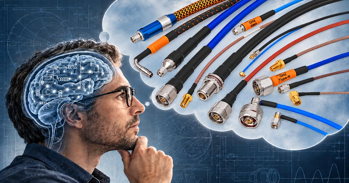
Why electrical performance, mechanical reliability and installation constraints should be considered together and tradeoffs weighed carefully.
An RF cable assembly may be a small component in a much larger system, but its performance can have an outsized effect on the result. An assembly with too much insertion loss can reduce the signal reaching a receiver. A cable that is difficult to route can delay installation or place stress on a connector. An assembly that performs well on the bench may develop intermittent problems when exposed to vibration, temperature changes or repeated movement.
These problems often begin with the same mistake: treating the cable assembly as a component to select after the rest of the system is designed, rather than as an interconnect that must satisfy electrical, mechanical and environmental requirements at the same time. Here are six common mistakes and practical ways to avoid them.
1. Selecting a cable without establishing an assembly level loss budget
“Low loss” is a useful description, but it is not a complete specification. Insertion loss depends on frequency, cable construction and length. Connectors and transitions also contribute to the performance of the finished assembly. A cable that looks suitable based on attenuation per foot may exceed the system’s allowable loss once the actual route and connector combination are considered.
This becomes especially consequential at higher frequencies, where an increase in cable length can consume a meaningful portion of the available signal budget. In a receive path, cable loss reduces the signal reaching the receiver. In a transmit path, less power reaches the antenna or other destination.
Solution: Start with the allowable loss then design the route
Establish the maximum acceptable insertion loss for the complete assembly at the relevant operating frequencies. Then evaluate cable type, actual length and connectors against that budget.
For example, if a cable is specified at an illustrative 1.0 dB per foot at the operating frequency, a two-foot length contributes approximately 2.0 dB of cable attenuation before connector and other assembly effects. Adding another foot increases the cable contribution to approximately 3.0 dB. A larger, lower-loss cable may reduce attenuation while increasing weight, bend radius and routing difficulty. The goal is an assembly that meets the loss budget and fits the system.
- What is the maximum allowable insertion loss at each critical frequency?
- What is the installed cable length, including bends and service requirements?
- Does the specification apply to the finished assembly or only the cable?
- How much margin is needed for manufacturing variation, temperature and the rest of the signal path?
- Would a shorter route or a different cable construction provide a better overall result?
2. Choosing the smallest cable without considering the trade offs
When space and weight are limited, it is tempting to select the smallest cable that appears to meet the frequency requirement. Smaller cable can be valuable, but diameter alone does not determine whether an assembly is the best fit. A smaller cable may offer tighter routing and lower weight, while a larger cable may offer lower attenuation or greater power-handling capability. Those relationships depend on the specific construction and should be checked against product data.
The smallest cable can become a false economy if higher loss requires a shorter route, a different system architecture or additional signal compensation.
Solution: Evaluate size weight and performance as a system
Compare candidate assemblies using insertion loss at the installed length and operating frequency, cable diameter and weight, minimum bend radius, frequency range, power handling, mechanical durability, environmental exposure and connector availability.
For a UAV, reducing cable weight is valuable—but not if it causes unacceptable signal loss or creates an installation that is difficult to maintain. A slightly larger cable might reduce attenuation enough to improve system performance, while a smaller cable might make sense for a short internal connection where the loss difference is negligible.
3. Underestimating the cable to connector transition
The point where the cable enters the connector is one of the most mechanically demanding areas of an assembly. The connector is relatively rigid; the cable may be bent, pulled, vibrated or moved. If those forces concentrate immediately behind the connector, they can stress the termination or damage the cable. The result may be degraded RF performance, an intermittent fault or a mechanical failure.
This can happen even when the cable itself meets its published bend-radius specification. The allowable bend location near the connector and any required straight section are also important. In a crowded enclosure, a sharp turn behind the connector may leave a continuous side load on the termination or equipment port.
Solution: Design the transition for the actual load
Provide space for a controlled bend. Route the cable so its bend begins in the appropriate location, within the assembly manufacturer’s specified limits. Support it where necessary to prevent its weight or movement from loading the connector.
Use a right-angle connector. A right-angle interface changes the cable exit direction and can reduce clearance behind a port. Check frequency rating, size and orientation, and make sure the cable can be installed without twisting it.
Add strain relief or bend protection. A properly designed molded elastomer or plastic boot, heat-shrink transition, spring guard or other protective feature can help manage bending or protect the cable near the connector. Select the feature for the force it must address: bend relief, pull-load management and abrasion protection are related but distinct functions.
Consider a tight-bend assembly. ConductRF TITE-BEND™ assemblies use a solderless termination approach and are intended for compact routing applications. For a constrained design, they may offer an alternative to a longer conventional connector transition or a right-angle connector. The allowable bend location, bend radius and mechanical performance must be confirmed for the selected assembly. A solderless termination does not eliminate every failure mode or provide unlimited flex life.
Where can the bend begin relative to the connector?
How much straight cable is needed behind the termination?
Will the cable be pulled, flexed or vibrated in service?
Is the connector or equipment port carrying a side load?
Would a right-angle connector, protective boot or TITE-BEND assembly improve routing?
4. Confusing a one time bend with repeated flexing
A cable that can be bent into position is not necessarily designed to flex repeatedly during operation. Flexible, hand-formable, semi-flexible and semi-rigid constructions offer different combinations of routing behavior, shape retention and mechanical performance.
A fixed internal route may need to be formed during installation and then remain in place. A test cable connected to a frequently repositioned device—or an assembly routed through a moving mechanism—experiences a different duty cycle. Repeated movement can affect the cable or termination if the assembly was not designed and qualified for that use.
Solution: Specify how the cable will move throughout its life
Describe the real motion: whether the cable is formed once or repeatedly moved, where movement occurs, the tightest bend during motion, expected cycles, and any twisting, vibration or pulling. Ask the supplier for relevant static and dynamic bend limits and any applicable flex-life or performance data. A tighter static bend limit should not be assumed to apply to continuous flexing.
For measurement applications, consider phase and amplitude stability with flex. If a test cable changes electrically as it is moved, the change can appear in the measurement and increase uncertainty. ConductRF’s True VNA families address different test-frequency and handling needs, including applications involving frequent repositioning.
5. Specifying the connector interface without checking the entire assembly
A connector name alone does not establish the performance of the finished assembly. The usable frequency range depends on the specific connector, cable, termination and assembly construction. The lowest-rated component can limit the assembly, while the interaction of all components affects insertion loss and return loss across the operating band. Connector configuration, mating quality and installation also matter.
Mechanical compatibility deserves the same attention. Two assemblies may use the same connector series but differ in gender, mounting style, coupling mechanism or orientation.
Solution: Specify and verify the finished assembly
For each end, define the connector interface and gender, straight or right-angle configuration, required frequency range, mating interface, mounting or coupling requirements, relative orientation when both ends are right-angle, and any mating-cycle or environmental requirements.
Specify the electrical performance required of the completed assembly, including insertion loss and VSWR or return loss over the relevant frequency range. Avoid relying on the theoretical capability of a connector family as a substitute for the actual connector and cable combination. Evaluate any adapters as part of the signal path.
6. Designing for the bench while overlooking the operating environment
An RF cable assembly can perform well during initial laboratory testing and still be poorly suited to its intended environment. The installed assembly may encounter vibration, temperature extremes, moisture, abrasion, cleaning chemicals, vacuum or repeated handling. Each condition can place different demands on the cable jacket, shielding, connector, termination and protective features.
Armor may improve resistance to crushing or abrasion, but it can also increase diameter, weight or bend radius. A jacket material chosen for one environment may not be appropriate for another.
Solution: Define the environment before selecting protective features
Document operating and storage temperatures; vibration and mechanical shock; moisture, outdoor exposure or immersion; abrasion and crushing; chemical exposure; vacuum or other application-specific conditions; and handling, maintenance and expected service life.
Select the cable construction, connector, jacket, sealing and protection to match those conditions. Where a requirement is critical, specify the applicable test method or acceptance criteria rather than relying on broad terms such as rugged, waterproof or high temperature.
Ruggedization should be targeted to the threat. For example, ConductRF describes a stainless-steel spiral conduit armor used on TUFF-FLEX VNA™ test cables to protect against excessive bending and crushing forces. That feature serves a different purpose from a connector strain-relief boot or an environmental seal.
Conclusion: Bring the RF interconnect requirements together before finalizing the design of your RF cables
The best RF cable assembly satisfies electrical requirements while fitting the available space, surviving the operating environment and remaining practical to install and maintain. Start with a single requirements list covering:
Electrical: frequency range, insertion loss, VSWR or return loss, power and phase requirements.
Mechanical: cable length, diameter, routing envelope, bend location, movement and connector orientation.
Environmental: temperature, vibration, moisture, chemicals, abrasion and other exposures.
Installation and service: access, handling, mating cycles, cable support and replacement needs.
With those requirements in hand, engineers can compare cable and connector options before a routing problem or performance shortfall becomes a late-stage redesign. ConductRF’s MAESTRO™ RF Cable Composer can help engineers explore cable and connector combinations around electrical and mechanical requirements. ConductRF can also work with teams on custom assemblies, specialized protection and tight-routing solutions such as TITE-BEND.
Discuss your next RF cable assembly with ConductRF and identify the trade-offs before they become design constraints.
Related Content:
Editorial notes and sources
Suggested link from the UAV article: “Even a carefully selected RF cable can underperform if its routing, connector transition or operating environment is overlooked. Explore six common RF cable assembly design mistakes and how to avoid them.”
Suggested link back to the UAV article: “Learn how cable selection, routing and insertion loss affect UAV size, weight, power and cost objectives.”
SEO title: Six RF Cable Assembly Design Mistakes and How to Avoid Them
Meta description: Avoid common RF cable assembly mistakes involving insertion loss, bend radius, connector strain relief, cable movement and environmental protection.
Technical review before publication: Confirm the specific TITE-BEND solderless termination method, permitted bend location and radius, available connector configurations, and any supported flex-life claims. Those details will determine how specifically its benefits can be stated.
Related Content:
www.conductrf.com/blog/technical-articles/understanding-phase-stability-in-vna-test-cables
www.conductrf.com/specialized-test-cables/true-vna-rf-test-cables/tuff-flex-vna
Join our mailing list
Sign up for news, resources and tips, straight to your inbox.
We’re committed to developing the best RF Cable Assemblies and technical resources. Subscribe today. You won’t want to miss a thing.